Dieses Beispiel stellt hauptsächlich die Funktion pnf_ screw_extrude_pnf_v() vor. Der Hauptzweck dieser Funktion ist, Gewinde zu machen, aber sie kann für mehr als ISO-Gewinde verwendet werden. Ein Gewinde scheint eine komplexe Geometrie zu haben, und ich gebe zu, dass es nicht so einfach ist, die Punkte eines Gewindes zu berechnen, wie die Punkte eines Zylinders, aber die Faces zu berechnen, ist fast das gleiche, wie für einen Zylinder oder für jedes Objekt, das in Paare von Dreicken, die es umgeben, eingeteilt werden kann. Stelle Dir ein Gewinde als ein Profil vor, was um einen imaginären Zylinder gewickelt wird. Aus der Sicht der Faces macht es keinen Unterschied, ob die indizierten Punkte eine Form bilden, die gerade hoch geht oder sich spiralförmig dreht.
In pnf_screw_extrude_pnf_v() wird das Profil des Gewindes (z.B. ein Dreieck in einem ISO-Gewinde oder die Silhouette einer Person in einem Kunstwerk) als erster Parameter in Form eines Feldes mit Punkten in zwei Dimensionalen (x, y) übergeben, und wieder ist es nur eine Frage von Trigonometrie, die Positionen der Punkte einer sich windenden Extrusion dieses Polygons zu berechnen
Es gibt da nur ein Problem, das einen Unterschied macht, und das ist, dass wir zwei Enden haben, die ohne Verbindung zu einer Gegenseite geschlossen werden müssen. In dem Beispiel mit dem Rohr haben wir das Problem umschifft, indem wir an den Anfang zurückgingen, was hier jedoch nicht möglich ist. Hier drängt sich die Lösung auf, die Fläche für die beiden Stirnseiten zu triangulieren, aber dies ist nur eine von zwei Wahlmöglichkeiten, und die andere ist eigentlich viel interessanter, weil sie viele Möglichkeiten bietet.
The elegant solution would be a triangulation of the polygon and a kind of lid and floor consisting of the points and faces of the triangles. But how can we triangulate any polygon to get a valid ending on both sides?
Eine
An intermediate solution would be, to introduce a further parameter with the points and faces data that the user of the function would have to determine manually, but this is also not yet implemented. Why? Because it wasn’t yet necessary for me. All the threads I have yet implemented, have a soft start and ending and don’t require a flat surface in shape of the profile at start and end. To see why this makes a complex triangulation unnecessary, let’s try different tactics for triangulation. The most obvious tactic is to chose one of the points of the polygon as a center point all the other points have triangles going to. Another tactic would be to chose one middle point and connect all the other points with triangles.
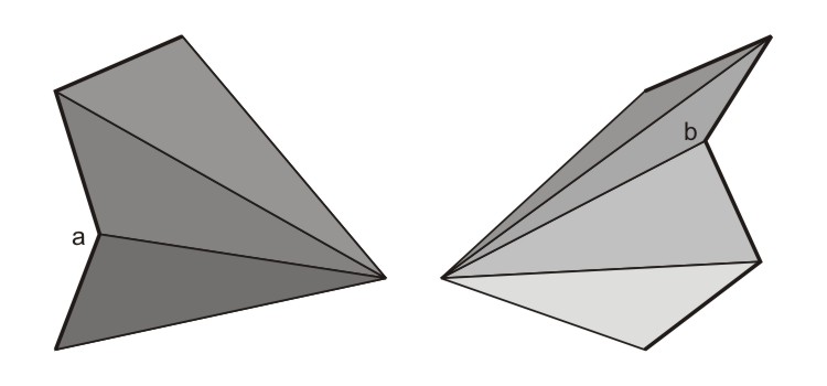
But neither work for any shape. What if there is an angle pointing to the inside?
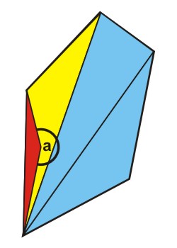
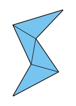
For the tactic of choosing one of the points it would be a disaster. The red triangle would be outside the polygon and furthermore it would be inside out. leaving it away would not be sufficient, because the yellow triangle still leaves the polygon. In this case, it would be sufficient, to choose the point with the inside angle (a) as the center point.
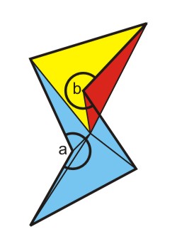
But what if there are two angles pointing inside? There are cases where it would still be sufficient to chose the right point, but there are also other cases, where there is no way to chose one point to connect the other points to.
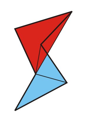
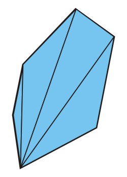
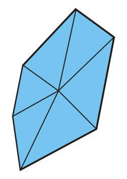
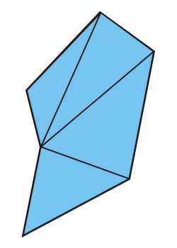
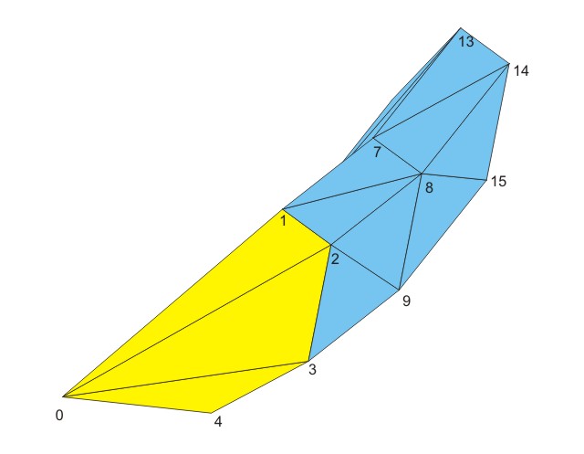
But what if we go into the third dimension? What if the middle point lies above the plane on which the polygon resides? As this webpage is a two-dimensional medium, I have to show you from two sides. Below you see two views of the example above with a middle point shifted into the third dimension.
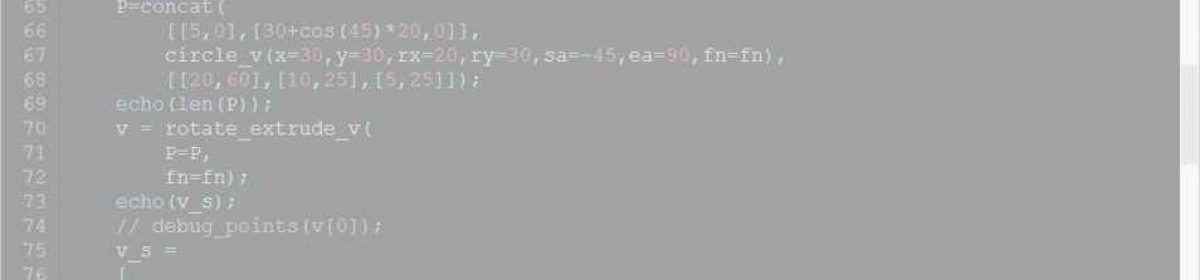
There is a function in pointsandfaces.scad, that connects one point to multiple others. It’s called concentric_faces_v() and it is very simple, but useful:
function concentric_faces_v(n,center,first,close=false) =
[
    for (i=[0:1:n-1])
    [
        center,
        first+i,
        first + (((i < n - 1) || (!close)) ? i + 1 : 0)
    ]
];
Note, that the order of the points determines, which is the inside and which is the outside of the object. For the start of the thread it should be all right. Our polygon has 6 edges, so the first parameter “n” is 6. The middle point of the start has the index 0, so the second parameter “center” is 0. The first point of the first ring is indexed by 1, so the third parameter “first” is set to 1 and “close” ist set to true, of course. For these values concentric_faces_v() returns the following 6 faces:
[[0, 1, 2], [0, 2, 3], [0, 3, 4], [0, 4, 5], [0, 5, 6], [0, 6, 1]].
The first face, which is [0, 1, 2], looks all right, the second and third, too. We cant see the other 3, but we can imagine them, and also the last (closing) face looks all right, [0, 6, 1] also defines the faces’ points in clockwise order, so the start of the thread looks all right.
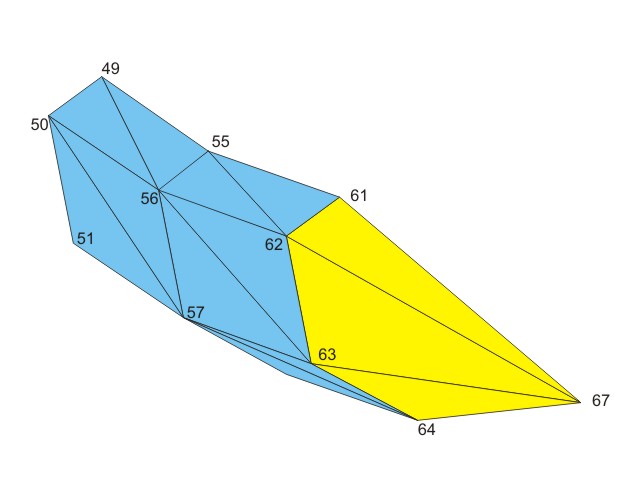
This is different with the ending of the thread. In this example the center point has the index 67, and the last ring before the end starts with 61. With these values concentric_faces_v() returns the following 6 faces:
[[67, 61, 62], [67, 62, 63], [67, 63, 64], [67, 64, 65], [67, 65, 66], [67, 66, 61]]
We can see immediately, that the points go anti-clockwise, and this is not what we want. We could change the function concentric_faces_v() to give it an additional parameter telling the index-difference between two points and set it to -1 or we can just flip the returned faces with turn_sides_faces_v(), which returns
[[62, 61, 67], [63, 62, 67], [64, 63, 67], [65, 64, 67], [66, 65, 67], [61, 66, 67]].
And this suits our needs. [62, 61, 67] goes clockwise, so do the other faces.
The middle point is also the end of the thread. In screw_extrude_pnf_v() the middle point is positioned in the center of the coordinate system of the polygon, thus if you place a thread on a cylinder, the polygon should be designed in a way that the side that touches the cylinder is positioned exactly on the y-axis and the little Overlap to avoid non-“watertight” objects is given by adding a very small value to the radius(es).
It requires only little additional calculation for the positions of the points to use this to implement soft thread-ends, because the polygon-data only has to be scaled at the beginning and end in a way, that can be defined by parameters. And there are quite a few parameters, because using this function in different situations I had the necessity to make it more flexibel. But let’s keep it simple, first:
use <inc/pnf/screwextrude.scad>

tol = 2;
fn = 256;
p = 30;

ScrewExtrude
(
    P=[[0,p/2-tol],[p,p/2-tol],[p,-p/2+tol],[0,-p/2+tol]],
    r=100, p=p, d=720, sr=90, erxy=90, erz=0, fn=fn, rf="sin"
);
In this case we use the wrapper module ScrewExtrude(), because unless you are Dali, you will probably not want to bend or forge threads and seldom use the function screw_extrude_pnf_v().
The Result is this:
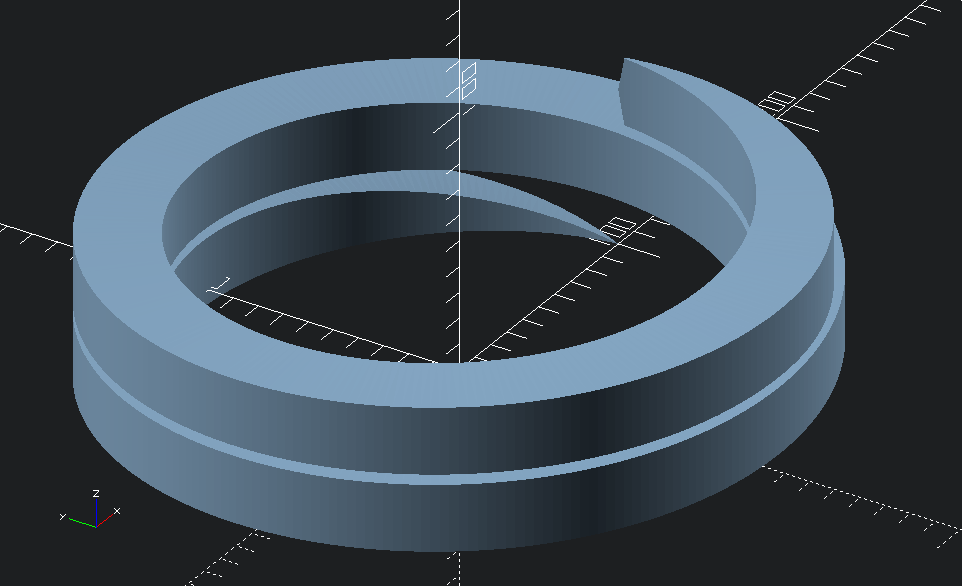
What catches the eye here is the different shapes of the both endings of this coil. This can be controlled with the “starting ramp” and “ending ramp” parameters sr, er, srxy, erxy, srz and erz. The lengths of the ramps can be different for the x/y-direction and the z-direction. The sr.. parameters tell the length of the respective ramp in degrees. We have 4 ramp dimensions:
| ramp | dimension | length-parameter | form-parameter |
| start | x/y | srxy | srfxy |
| start | z | srz | srfz |
| end | x/y | erxy | erfxy |
| end | z | erz | erfz |
The parameter sr is the default for srxy and srz, er is the default for erxy and erz.
This all doesn’t mean, that triangulation of polygons is not to be implemented in future. Actually, besides writing this documentation, taking care of house and daughter, I am currently experimenting with it, because I want to implement a linear_extrude_pnf_v() function, and it would also be a nice option for rotate_extrude_pnf_v(), to have flat endings, if desired.